555 Timer Schematic : 555 - 556 dual timer circuit not clear to me - Electrical ... / Nov 05, 2011 · schematic development, spice simulation, waveform viewer and many other features.
byAdmin•
0
555 Timer Schematic : 555 - 556 dual timer circuit not clear to me - Electrical ... / Nov 05, 2011 · schematic development, spice simulation, waveform viewer and many other features.. We're working on a simple led flasher that includes a 555 timer and some basic components. Derivatives provide two (556) or four (558) timing circuits in one package. The 555 timer can be obtained very cheaply from pretty much any electronic retailer. 2nd and 6th pins are shorted to allow triggering after every cycle. The breadboard schematic of the above circuit is shown below.
It produces pulses whose width can be varied. 2nd and 6th pins are shorted to allow triggering after every cycle. Oct 13, 2018 · the 555 timer ic is an integrated circuit used in a variety of timer, pulse generation and oscillator applications. The 555 timer can be obtained very cheaply from pretty much any electronic retailer. Jun 10, 2021 · there is a 555 timer application on this site to achieve the timings you need.
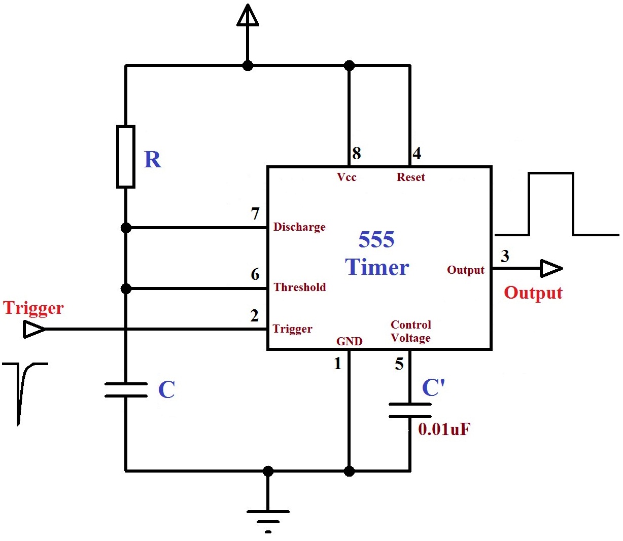
Monstable Multivibrator using 555 Timer from electrosome.com In this article, we cover the following information about 555 timer ic. We're working on a simple led flasher that includes a 555 timer and some basic components. 4th pin is connected to vcc to avoid sudden resets. Nov 05, 2011 · schematic development, spice simulation, waveform viewer and many other features. Jul 24, 2019 · the working principle of the 555 timer is by considering the block diagram of the 555 timer ic. The 555 timer ic is an integrated circuit (chip) used in a variety of timer, delay, pulse generation, and oscillator applications. Here's our schematic in its current shape. Jun 10, 2021 · there is a 555 timer application on this site to achieve the timings you need.
You may already know that se/ne 555 is a timer ic introduced by signetics corporation in 1970's.
4th pin is connected to vcc to avoid sudden resets. This article covers every basic aspect of 555 timer ic. We're working on a simple led flasher that includes a 555 timer and some basic components. The 555 timer is a chip that can be us… Nov 03, 2018 · 555 timer here, 555 timer runs in free running mode i.e. If you want to know all the pinout of the 555 timer, what each pin is and what each pin does, see 555 timer pinout. In this article, we cover the following information about 555 timer ic. 555 timer ic (16) 8051 (26) 8051 projects (21) amplifier circuits (39) It produces pulses whose width can be varied. With those details out of the way, let's jump into your schematic and get started! Jul 24, 2019 · the working principle of the 555 timer is by considering the block diagram of the 555 timer ic. You may already know that se/ne 555 is a timer ic introduced by signetics corporation in 1970's. In 2017, it was said over a billion 555 timers are pr.
The 555 timer is a chip that can be us… This article covers every basic aspect of 555 timer ic. Nov 03, 2018 · 555 timer here, 555 timer runs in free running mode i.e. 555 timer ic (16) 8051 (26) 8051 projects (21) amplifier circuits (39) The 555 timer ic is an integrated circuit (chip) used in a variety of timer, delay, pulse generation, and oscillator applications.
555 Logic Diagram - Wiring Diagram Networks from www.electronicsforu.com This tutorial provides sample circuits to set up a 555 timer in monostable, astable, and bistable modes as well as an in depth discussion of how the 555 timer works and how to choose components to use with it. In this circuit, we will connect the 555 timer to be in astable mode. You may already know that se/ne 555 is a timer ic introduced by signetics corporation in 1970's. This article covers every basic aspect of 555 timer ic. 4th pin is connected to vcc to avoid sudden resets. 555 timer ic (16) 8051 (26) 8051 projects (21) amplifier circuits (39) Oct 13, 2018 · the 555 timer ic is an integrated circuit used in a variety of timer, pulse generation and oscillator applications. Just check the pinouts of the pot.
With those details out of the way, let's jump into your schematic and get started!
Nov 05, 2011 · schematic development, spice simulation, waveform viewer and many other features. The 555 timer delay before turn off circuit we will build is shown below. It was commercialized in 1972 by signetics. Nov 03, 2018 · 555 timer here, 555 timer runs in free running mode i.e. The 555 timer ic is an integrated circuit (chip) used in a variety of timer, delay, pulse generation, and oscillator applications. This article covers every basic aspect of 555 timer ic. If you want to know all the pinout of the 555 timer, what each pin is and what each pin does, see 555 timer pinout. 555 timer ic (16) 8051 (26) 8051 projects (21) amplifier circuits (39) 4th pin is connected to vcc to avoid sudden resets. Oct 13, 2018 · the 555 timer ic is an integrated circuit used in a variety of timer, pulse generation and oscillator applications. The 555 timer can be obtained very cheaply from pretty much any electronic retailer. In this circuit, we will connect the 555 timer to be in astable mode. Just check the pinouts of the pot.
2nd and 6th pins are shorted to allow triggering after every cycle. 4th pin is connected to vcc to avoid sudden resets. With those details out of the way, let's jump into your schematic and get started! The 555 timer can be obtained very cheaply from pretty much any electronic retailer. Derivatives provide two (556) or four (558) timing circuits in one package.
555 Timer Assembly Instructions | Synthrotek from www.synthrotek.com We're working on a simple led flasher that includes a 555 timer and some basic components. The control input is used in some of the applications, but most of the applications the control input is not used hence the control voltage is equal to +2/3 vcc. Just check the pinouts of the pot. The 555 timer can be obtained very cheaply from pretty much any electronic retailer. In this circuit, we will connect the 555 timer to be in astable mode. If you want to know all the pinout of the 555 timer, what each pin is and what each pin does, see 555 timer pinout. It was commercialized in 1972 by signetics. Nov 03, 2018 · 555 timer here, 555 timer runs in free running mode i.e.
Just check the pinouts of the pot.
This tutorial provides sample circuits to set up a 555 timer in monostable, astable, and bistable modes as well as an in depth discussion of how the 555 timer works and how to choose components to use with it. The 555 timer can be obtained very cheaply from pretty much any electronic retailer. It produces pulses whose width can be varied. We're working on a simple led flasher that includes a 555 timer and some basic components. I have used two 555 timer ics in this project and both these 555 ics act as astable multivibrators. Jul 24, 2019 · the working principle of the 555 timer is by considering the block diagram of the 555 timer ic. The 555 timer is a chip that can be us… 555 timer ic (16) 8051 (26) 8051 projects (21) amplifier circuits (39) It was commercialized in 1972 by signetics. Oct 13, 2018 · the 555 timer ic is an integrated circuit used in a variety of timer, pulse generation and oscillator applications. You may already know that se/ne 555 is a timer ic introduced by signetics corporation in 1970's. Its not listed anymore, but i can still link it in. Nov 05, 2011 · schematic development, spice simulation, waveform viewer and many other features.